FIRST STEPS

STARTING
FIRST STEPS

STARTING
To explain the use of Icem CFD, a very simple case will be show. This example is a cube of one meter side. One side would be an input and the opposite would be an output. The other sides would be some walls.
When you start Icem CFD, this principal window appears.

| A window named "select project" allows to create a new project or to use an existing one. You click on the button "Accept". |
|

CREATE A GEOMETRY
To create a geometry, you must use Icem CFD DDN. So you select "Geometry / CAD Tools / DDN".

| Then a window "Select ddn part" appears and allows you to
create a new geometry or to selecting an existing one.
For this example, you type the name of the ddn part, next you click on the button "Accept". |
|
Icem CFD DDN starts and the work window of DDN appears.
To learn how operates the mouse, you can go to the page "Tips".
|
Firstly, you must create some points. So, you click on the button "point". Then, you click on the button "XYZ" in the new toolbar. Then, you enter the coordonates of the point and you validate ("xxx", enter, "yyy", enter, "zzz", enter, "]").
|
|
|
|
You do the same for all the other points ("0., 0., 0." ; "1., 0., 0." ; "1., 1., 0." ; "0., 1., 0." ; "0., 0., 1." ; "1., 0., 1." ; "1., 1., 1." and "0., 1., 1."). You obtain this figure. |
| Next, you must create some lines. So, you click on the button "line". Then, you click on the button which looks like two point linked by a line. |
|
|
|
Then you can click on two points and validate to create a line. You do the same for the 12 lines of the cube. You obtain this result. |
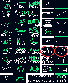
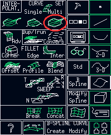
Next you must create some planes. So, you click on the button "plane". Then, you click on the button "B-spline" in the new toolbar. So a new toolbar appear and you click on the button which looks like a meshing area.


Then, you must click on the lines which are all around a surface and you validate. You do the same for all the sides of the cube. You obtain this result. |
|
|
|
Finally, you must create a new point in the cube. This point must be in the domain which will be meshed.
|
You can now save the geometry. So you click on the button "files". Next you click on the button "Quit" in the new toolbar. The principal window of Icem CFD reappears.


DEFINITION OF THE BOUNDARY CONDITIONS
| To create the boundary conditions, you must use Icem CFD DDN => Tetin. So you select "Geometry / DDN Tools / DDN => Tetin". Then a window "Select ddn part" appears and allows you to create a new geometry or to selecting an existing one. |
|
|
|
A new window appears. This is the same than the window of DDN, but the text is different. |
Firstly, you must create the families. So you click on "families", then on "families - add". Now you type the name of each family and you validate ("input", "out", "wall", "fluid", "]").

Next you must associate the elements with the families. So you click on "families", then on "entity - add". You select now a family (for example : "input") and the elements which belong to this family (the surfaces, the lines and the points) and you validate. You do the same for all the families, except the family "fluid".
To select lines or points, you can hide the surfaces and the lines. To learnt how to hide some elements, go to the page "Tips".
To define the domain "fluid", you click "domains", then "create material domain". You select now the family "fluid", next you click on the point in the cube and you validate.

Finally, you click on "file / exit", next on "file - exit". So the boundary conditions are saved and the principal window of Icem CFD reappears.

THE HEXAHEDRAL MESHER
Above the principal window, another window named "Tetin file" appears. You select the geometry (tetin file) which you want to mesh.
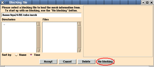
Then you select the hexahedral mesher (Hexa / Interactive). A window named "Blocking file" appears. You click on the button "No blocking". A window named "Icem HEXA ICEM CFD" appears. As the cube is a very simple geometry, the only block is the cube. So no blocking is necessary.

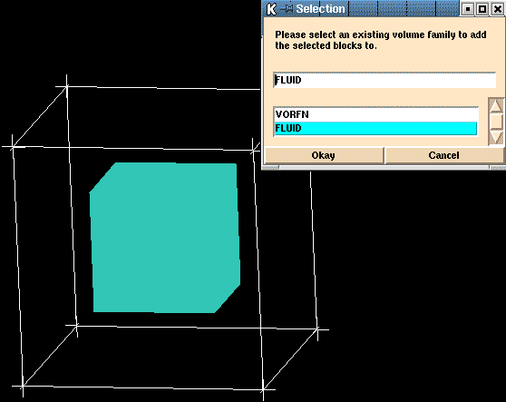
You must now associate the block and the material. So you select the toolbar "Blocking", next you click on the button "Material" and finally on "Select Block".

A Window named "Selection" appears. You click on "Fluid" because "VORFN" is the volume which must not be meshed. Then you click on the cube.

|
Then, you must choose the parameters of the mesh. You
select the toolbar "Meshing" and you click on the button "Edge
params". A window named "Edge meshing parameters" appears. You must
define the parameters. So you select an edge, next you define the number of
point.
|
|
|
|
To see the mesh, you must click on "Mesh" in the window "Display". |
| To save the mesh, you select the toolbar "File". You choose the different parameters of the mesh (Structured / Unstructured ; Hexahedral / Tetrahedral ...) and you click on the button "Save blocking". You must unselect the option "Save picture of blocking" and the you click on the button "Accept". So your mesh is saved if you want to use it a new time. |
|
But to export your mesh to ICEM CFD, you must to click on the button "Multiblock" or "Unstructured" or "Unstr Surface".


| When you quit
the mesher to return to Icem CFD, a window named "Selection"
appears. You must also choose what grid you want to use.
To export the mesh to a CFD software, you can go to the page "Tips" |
|
january 2002.